RJ-45 conductor data cable contains 4 pairs of wires each consists of a solid colored wire and a strip of the same color. There are two wiring standards for RJ-45 wiring: T-568A and T-568B. Although there are 4 pairs of wires, 10BaseT/100BaseT Ethernet uses only 2 pairs: Orange and Green. The other two colors (blue and brown) may be used for a second Ethernet line or for phone connections. The two wiring standards are used to create a cross-over cable (T-568A on one end, and T-568B on the other end), or a straight-through cable (T-568B or T-568A on both ends).
|
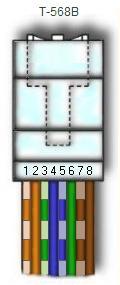
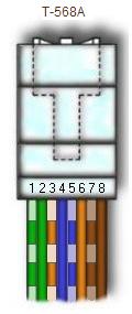
To create a straight-through cable, you'll have to use either T-568A or T-568B on both ends of the cable. The diagram depicted on the left and right shows clip of the RJ-45 connector down. To create a cross-over cable, you'll wire T-568A on one end and T-568B on the other end of the cable. The straight-through cables are used when connecting Data Terminating Equipment (DTE) to Data Communications Equipment (DCE), such as computers and routers to modems (gateways) or hubs (Ethernet Switches). The cross-over cables are used when connecting DTE to DTE, or DCE to DCE equipment; such as computer to computer, computer to router; or gateway to hub connections. The DTE equipment terminates the signal, while DCE equipment do not. |
|
More on straight-through and cross-over connections
The RJ45 data cables we use to connect computers to a Ethernet switch is straight-through cables. As noted above, the RJ45 cable uses only 2-pairs of wires: Orange (pins 1 & 2) and Green (pins 3 & 6). Pins 4, 5 (Blue) and 7, 8 (Brown) are NOT used. Straight-through cable, as its name suggests, connects pin 1 to pin 1, pin 2 to pin 2, pin 3 to pin 3, and pin 6 to pin 6. Cross-over cables are used to connect TX+ to RX+, and TX- to RX-, which connects pin 1 to pin 3, pin 2 to pin 6, pin 3 to pin 1 and pin 6 to pin 2. The unused pins are generally connected straight-through in both straight-through and cross-over cables.
To network two computers without a hub, a cross-over cable is used. Cross-over cable is also used to connect a router to a computer, or ethernet switch (hub) to another ethernet switch without an uplink. Most ethernet switches today provide an uplink port, which prevents a use of cross-over cable to daisy chain another ethernet switch. Straight-through cables are used to connect a computer to an ethernet switch, or a router to an ethernet switch.
Pin Number Designations
There are pin number designations for each color in T-568B and T-568A.
                 T-568B                         T-568A
       --------------------------      ------------------------
Pin    Color             Pin Name      Color           Pin Name
---    -------------     --------      -------------   --------
 1     Orange Stripe     Tx+           Green Stripe    Rx+
 2     Orange            Tx-           Green           Rx-
 3     Green Stripe      Rx+           Orange Stripe   Tx+
 4     Blue              Not Used      Blue            Not Used
 5     Blue Stripe       Not Used      Blue Stripe     Not Used
 6     Green             Rx-           Orange          Tx-
 7     Brown Stripe      Not Used      Brown Stripe    Not Used
 8     Brown             Not Used      Brown           Not Used
RJ45 Color-Coded Scheme
RJ45 cables have 8 color-coded wires, and the plugs have 8 pins and conductors. Eight wires are used as 4 pairs, each representing positive and negative polarity. The most commonly used wiring standard for 100baseT is T-586B stanrard described above. Prior to EIA 568A and 568B standards, the color-coded scheme was used to wire RJ45 cables. The table below depicts pin and color schemes used in traditional and standardized setup.
| Pin | Colored Scheme | T-568B (Common) | T-568A |
|---|---|---|---|
| 1 | Blue | Orange Stripe | Green Stripe |
| 2 | Orange | Orange | Green |
| 3 | Black | Green Stripe | Orange Stripe |
| 4 | Red | Blue | Blue |
| 5 | Green | Blue Stripe | Blue Stripe |
| 6 | Yellow | Green | Orange |
| 7 | Brown | Brown Stripe | Brown Stripe |
| 8 | White (or Grey) | Brown | Brown |
RJ-45 Wiring FAQ
1. What are T-568A and T-568B wiring standards, and how are they different?
T-568A and T-568B are the two wiring standards for RJ-45 connector data cable specified by TIA/EIA-568-A wiring standards document. The difference between the two is the position of the orange and green wire pairs. It is preferable to wire to T-568B standards if there is no pre-existing pattern used within a building.
2. What is RJ stands for?
RJ stands for Registered Jacks. These are used in telephone and data jack wiring registered with FCC. RJ-11 is a 6-position, 4-conductor jack used in telephone wiring, and RJ-45 is a 8-position, 8-conductor jack used in 10BaseT and 100BaseT ethernet wiring.
3. What is the Category Rating System?
Electronic Industries Association (EIA) developed the TIA/EIA-568-A standard, which specifies wiring and performance standards for Unshielded Twisted Pair (UTP) cabling. Category Rating System specifies the definition of performance categories for 100 ohm UTP cabling system.
Category 3 specifies the twisted pair cable and connecting hardware that can support transmission frequency up to 16MHz, and data rates up to 10Mbps. This is primarily used in telephone wiring.
Category 4 specifies cables and connectors that supports up to 20MHz and data rates up to 16Mbps. With introduction of category 5, this is a rarely used category.
Category 5 specifies cables and connectors that supports up to 100MHz and data rates up to 100Mbps. With 100BaseT Ethernet today, Category 5 is a widely used cabling system that matches todays high-speed data requirements.
| Category | TIA/EIA Standard | Description |
|---|---|---|
| Cat 1 | None | POTS, ISDN and doorbell wiring |
| Cat 2 | None | 4 Mbps token ring networks |
| Cat 3 | TIA/EIA 568-B | 10 Mbps Ethernet - frequency up to 16MHz |
| Cat 4 | None | 16 Mbps token ring networks - frequency up to 20MHz |
| Cat 5 | None | 100 Mbps Ethernet - frequency up to 100 MHz Not suitable for GigE (1000BaseT) |
| Cat 5e | TIA/EIA 568-B | 100 Mbps & GigE Ethernet - frequency up to 100 MHz |
| Cat 6 | TIA/EIA 568-B | 2x Performance of Cat 5 & 5e - frequency up to 250 MHz |
| Cat 6a | None | Future specification for 10Gbps application |
| Cat 7 | ISO/IEC 11801 Class F | Designed for transmission at frequencies up to 600 MHz |
4. What is UTP Cable?
UTP stands for Unshielded Twisted Pair. It is the cabling system with one or more pairs of twisted insulated copper wires contained in a single sheath. It is the most widely used cabling system in telecommunications and data communications environment today.
Conclusion
The RJ-45 wiring standards, T-568A and T-568B, play a critical role in establishing reliable network connections for both data and voice transmission. Understanding the distinctions between straight-through and cross-over cables ensures compatibility with various equipment setups, such as DTE to DCE or DTE to DTE connections.
By adhering to the appropriate wiring schemes and pin configurations, businesses and individuals can optimize their network's performance while minimizing potential errors. Whether for professional use or home networking, mastering the basics of RJ-45 cabling empowers users to create efficient and scalable systems.
As network demands evolve, staying informed about cable standards and advancements in Ethernet technology will remain crucial for seamless communication and connectivity. Proper implementation of these standards not only supports current requirements but also prepares networks for future expansions.
Share this post
Leave a comment
All comments are moderated. Spammy and bot submitted comments are deleted. Please submit the comments that are helpful to others, and we'll approve your comments. A comment that includes outbound link will only be approved if the content is relevant to the topic, and has some value to our readers.
Comments (0)
No comment